
Huh? Tubes Running with 12V on the Plates?
Yup. That, or even less. You don't have to risk your skin building 250V power supplies just to build a simple radio receiver with tubes. Note well that this applies almost exclusively to receivers. Getting any significant amount of power out of a tube—more than about fifty milliwatts—requires voltages that edge up into lethal territory. But if you've got or can acquire a pair of headphones, getting started can be done on 12V or less.
There are two tricks that make this possible:
- Some tubes have always had the ability to work at low voltages. Engineers used high voltages for them because the power tubes elsewhere in the circuit required it, and the high voltage was already there in the design. But with a properly designed circuit, you can run some tubes on as little as 3V. This beggars conventional wisdom about tube operation, but it's true.
- A line of tubes was designed from scratch for efficient use entirely at 12V, both plates and filaments.
Let's talk about the tubes designed specifically for 12V operation first.
"Space Charge" Tubes for Car Radios
Way back in the late 1950s, engineers at Tung-Sol decided to do away with vibrator power supplies in car radios. Vibrators were plug-in modules roughly the size and shape of octal tubes, which created an interrupted DC current using a solenoid coil and reed-style contacts. The interrupted DC current allowed a step-up transformer to accept a 12V input and produce the 180V output required by conventional vacuum tubes. Vibrators were noisy (both at audio and at RF) and because of arcing across their contacts had a finite life and had to be replaced periodically. The transistors of the time weren't as good (nor as cheap) as they needed to be, especially at RF. So instead of using late 50's not-quite-ready-for-prime-time transistors, Tung-Sol created a line of tubes that could work with a car-battery plate voltage of 12V, which by 1958 had become ubiquitous in new American cars.
These tubes worked on something called the "space charge" principle, which basically used the first grid after the cathode to accelerate electrons toward the weakly-charged plate, which was now working at 12V instead of 180V. Between 1958 and 1962 Tung-Sol, GE, RCA and other manufacturers released quite a few different types, all in 7- and 9-pin miniature packages. Virtually all of these tubes were designed for RF work up to reasonable HF frequencies. Note that there are no true power amplifiers in the lineup. Getting a tube to output significant power with 12V on the plate is almost impossible. Nonetheless, if you're content with headphones or QRP operation, the space-charge 12K5 driver tube can source as much as 35 milliwatts at either audio or RF.
Note also that conventional high-voltage tetrode tubes can be used in space-charge mode at 12V, but the high capacitance between the second grid and the plate make them function poorly compared to tubes designed specifically for space charge operation. Nonetheless, reasonably effective circuits have been published using classic tubes like the Type 49. (I'll provide pointers to numerous circuits later on this page.)
There are a few tubes that
blur the difference. I've heard a couple of people say that the 12U7
dual triode is basically the same tube as a 12AU7 dual triode with a
little more gain.
The
main reason to use
space-charge tubes is
that they do not require dangerous voltages to operate. Both the
filaments and the plates run at 12V, so your risk of shock while
testing and using your projects is virtually nil. In the past 40 years
or so we've gotten very used to poking our
solid-state projects with our fingers, forgetting the "one hand in the
pocket" rule and general caution around high voltages that kept us all
alive when tubes had 180V, 280V, or even 450V on the plates. The idea
is to present a technology that you can work on with your kids (or
encourage them to explore on their own) without fretting about shock
hazards.
Space-Charge Tubes and Tube Data
Below is a list of all the space-charge tubes that I have discovered. Others may exist, especially from non-North American sources. Left-margin links to tube data are to the wonderful NJ7P Tube Data Site. The data PDFs are from wherever I can find them.) If you know of any other tubes specifically designed for 12V or less on the plate, please let me know!
- 6GM8 -- Twin Triode with 6.3V on filaments and plates (Data PDF)
- 12AC6 -- Remote Cutoff Pentode (Data PDF)
- 12AD6 -- Pentagrid Converter (Data PDF)
- 12AE6 -- Dual Diode & Medium-Mu Triode (Data PDF)
- 12AE7 -- Medium-Mu Triode & Lo-Mu Triode (Data PDF)
- 12AF6 -- Remote-Cutoff Pentode (Data PDF)
- 12AG6 -- Pentagrid Converter (Data PDF)
- 12AJ6 -- Dual Diode & Hi-Mu Triode (Data PDF)
- 12AL8 -- Medium-Mu Triode & Power Tetrode (Data PDF)
- 12BL6 -- Remote-Cutoff Pentode (Data PDF)
- 12CN5 -- Remote-Cutoff Pentode (Data PDF)
- 12CX6 -- Remote-Cutoff Pentode (Data PDF)
- 12CY6 -- Remote-Cutoff Pentode
- 12DE8 -- Diode & Remote-Cutoff Pentode (Data PDF)
- 12DK5 -- RF Pentode
- 12DK7 -- Dual Diode & Power Tetrode (Data PDF)
- 12DL8 -- Dual Diode & Power Tetrode (sep. cathodes) (PDF)
- 12DS7 -- Dual Diode & Power Tetrode (Data PDF)
- 12DU7 -- Dual Diode & Power Tetrode (Data PDF)
- 12DV7 -- Dual Diode & Power Tetrode (Data PDF)
- 12DV8 -- Dual Diode & Power Tetrode (sep. cathodes) (Data PDF)
- 12DW8 -- Diode & Dissimilar Dual Triode (Data PDF)
- 12DY8 -- Medium-Mu Triode/Remote-Cutoff Tetrode (PDF)
- 12DZ6 -- Remote-Cutoff Pentode (With Curves) (Data PDF)
- 12EA6 -- Remote-Cutoff Pentode (Data PDF)
- 12EC8 -- Med.-Mu Triode/Semiremote Cutoff Pentode (9 pin) (PDF)
- 12EG6 -- Dual-Control Heptode (Pentagrid Amplifier) (Data PDF)
- 12EK6 -- Remote-Cutoff Pentode (Data PDF)
- 12EL6 -- Dual Diode & Hi-Mu Triode (Data PDF)
- 12EM6 -- Diode & Power Tetrode (Data PDF)
- 12EZ6 -- RF Pentode (Data PDF)
- 12F8 -- Dual Diode & Remote-Cutoff Pentode (Data PDF)
- 12FA6 -- Pentagrid Converter (Data PDF)
- 12FK6 -- Dual Diode & Lo-Mu Triode (With Char. Curves) (Data PDF)
- 12FM6 -- Dual Diode & Medium-Mu Triode (Data PDF)
- 12FR8 -- Pentode & Triode & Diode (Data PDF)
- 12FT6 -- Dual Diode & Triode (Data PDF)
- 12FX8 -- Medium-Mu Triode & Pentagrid Converter (Data PDF)
- 12GA6 -- Pentagrid Converter (Data PDF)
- 12F8 -- Dual Diode & Remote-Cutoff Pentode (Data PDF)
- 12G8 -- Dual Triode
- 12J8 -- Dual Diode & Power Tetrode (Data PDF)
- 12K5 -- Power Tetrode (Data PDF)
- 12U7 -- Dual Medium-Mu Triode (9 pin) (Data PDF)
- 8056 -- High-Frequency Triode (Nuvistor) (Data PDF in German)
Tech Tips for Space-Charge Tubes
The best way to get a sense for space-charge tubes is to study some real circuits. Look at the online circuits listed below, and see if you (or one of your friends) have any of the older print articles listed after the online articles. That done, choose a simple circuit for a "learning project" and just have at it! That said, here are some tips:
-
Be aware that these tubes (with the possible exception of the type 8056 nuvistor) draw a lot of current at 12V, sometimes almost half an amp. (Virtually all of this goes into heating the cathode.) If you put three or four in a circuit, you had better be able to supply 12V at two or three amps. This is easy in a car; not always so easy on a test bench. I don't recommend making up space-charge portable radios using AA cells!
-
Avoid grid confusion! The first grid (the grid physically closest to the cathode; what in conventional tubing is called the control grid) should be tied to 12V. If you're using a conventional tetrode or pentode in space-charge mode, make sure you put 12V on the control grid, and use the screen grid as the control grid. Pentode suppressor grids are almost always tied internally to the tube cathode, but if the suppressor grid comes out separately to a pin, try putting 12V on the suppressor as well. This may allow greater gain in some circuits, as you have two grids accelerating electrons toward the weakly charged plate.
-
If the tube you're using has one or more diode sections that are not part of the circuit you're building, tie the diode plates to ground.
-
Biasing is not anything like biasing when your B+ is in the 150-200V range. Don't just drop a 12V tetrode or pentode into a circuit designed for a 180V tubes. Try to find some of the articles I list below and study the circuits. It's not that they're more complex. (Generally, you'll find them simpler!) They're just different.
-
If you possibly can, find a copy of an early 1960's RCA receiving tube handbook. This will give you tech specs on all the tubes, plus a couple of "reference model" circuits (usually car radios) to stare at. Antique Electronic Supply in Arizona sells reprints of the 1959 and 1973 editions, both of which are worth having. The 1973 edition (probably one of the last) has all the 12V tubes listed above.
Low-Voltage Operation With Ordinary Tubes
Keep in mind that a lot of "ordinary" high-voltage tubes can be used very effectively with DC voltages as low as 3V on the plates. Some of these tubes can be operated in "space-charge" mode with the first grid used as an electron accelerator, but that's not entirely necessary. I cite some circuits below with ordinary triodes operating at very low voltages.
The
problem with tubes generally is that taking power out of a tube circuit
requires operating at a high voltage. If you don't need significant
output power (say, for a loudspeaker) and can settle for very low
values of plate current, you can use plate voltage values under 20V,
and often less than 10V. When building radio receivers, this generally
requires using high-impedence headphones for audio output, where
"high-impedence" means 600 ohms or more at audio, the higher the
better. Such headsets are getting increasingly hard to find; Antique
Electronic Supply used to sell them, but do not show them in the
2007-2008 catalog or later. I do see them regularly on eBay. You can also try military surplus outlets like Fair Radio Sales.
Crystal earphones are also high impedence and can be used, with one gotcha: They do not pass DC. In many older circuits, the plate voltage passes through the headphones, which requires a dynamic headset (that is, one with wire-wound transducers) rather than a crystal transducer. For an example, scroll down to the schematic for KB7NRN's 18V radio. A crystal earphone will not work in this circuit, nor any circuit that passes B+ to the plate of the tube (or anywhere else) through the headset.
Many of the circuits you'll find in books and magazines specify 45V, 67.5V, or 90V batteries, which can still be had but are expensive. A lot of those circuits will work just fine on much lower voltage. For example, I built the 3V4 BCB receiver from Harry Zarchy's kid-hobby book Using Electronics, and the circuit has a 100K resistor in series with the regen control pot. The resistor was necessary because the specified 45V battery supply was too high. Without the resistor, the receiver oscillated at 45V irrespective of the setting of the regen pot—and worked perfectly at 9V, using an ordinary (and cheap) transistor radio battery.
I use a beat-up "hamfest special" adjustable lab supply for simple tube radio work, and I can spin a knob to vary the voltage between 0 and 50V. When I have a circuit on the bench spec-ed for 45V B+, I set the supply at 45V, make sure the circuit works, and then start dialing down the voltage to see what happens. Most of the time, increasing the amount of regeneration on receiver's throttle control will compensate for the reduction in voltage. Sometimes (as with Zarchy's circuit) you have to tweak component values a litttle to get down under 10V B+, but with decent headphones and a good antenna you will get signals. The art lies in tweaking things to get the most signal at the least plate voltage.
Drawing Your Own Tube Schematics with Visio
If you modify published tube circuits before you build them, it's always a good idea to redraw them so you don't forget how the circuit on the bench differs from the one in that old article in QST. There's a very nice drawing program called Visio (now owned by Microsoft) that I've been using to draw schematics for over ten years now. Older versions can be had on eBay for as little as $20, and in fact the version I use—Visio 2000—is now seven years old and still perfectly useful. (The latest versions require product activation, which I cannot abide, but in truth there's little in the newest Visio versions that isn't in Visio 2000. Just don't use Visio 1.0)
I created a stencil file full of tube pinouts, including all the common tube types (dual diode, triode, tetrode, pentode, and so on) and all you need to do is drag them off the stencil and start connecting the leads. (Visio comes with stencils for all the common components like resistors, capacitors, and inductors.)
You can download the stencil file here. It has stencils for the several earlier versions of Visio, but the Visio 5 stencil works fine with Visio 2000 and later versions. Here's an example of a schematic I drew with the stencil. (285K GIF.)
Low-B+ Tube Articles and Circuits on the Web
-
12V Space Charge Superhet by Mike Starcher. An original circuit (the schematic is present in a crisp PDF) and beautiful construction, with very clear photos. The seven tubes in the lineup include three 12AF6es, a 12AD6, a 12AE6, and a pair of 12K5s operating in parallel for audio power output. (Using a modern speaker with a large magnet also helps with volume.) All parts should be obtainable from sources like Antique Electronics Supply. Slightly off-topic here, but also note Mike's 1-transistor reflex regen, which is an amazing circuit, based on the wonderfully named Macrohenrydyne.
-
The Lamphouse Hiker's One and Its Derivatives. From the late 1930s to the early 1950s, a New Zealand radio parts and kits catalog called The Lamphouse Annual published circuits for a series of regenerative receivers called the Hiker's, after the name of the first circuit published, "The Hiker's One." (The "One" meant "one tube.") The Hiker's receivers worked on the space charge principle, using the venerable Type 49 and later farm radio tubes like the 1Q5, with 18V on the plates. This site presents scans of several of the Hiker's radios, plus commentary. Note: The site is very IE-specific, and will not render correctly with Firefox or Opera.
-
Hiker's Two by KB7NRN. A pair of 3Q5 farm radio tubes with 18V on the plates makes for a very nice radio, especially when constructed with the care that John KB7NRN does here. It's one of the most beautifully constructed units I've ever seen displayed on the Web. Catch that enormous old horn speaker! (As with the above page, this one is IE-specific and does not render correctly with Firefox or Opera.)
- The Haynes Pocket Receiver. By George V. Dubuc. The piece was published in the November 1937 Radio World, which can be had in its entirety from the Internet Archive. (The link here is to the full magazine. The article is on p. 26.)
The radio uses a type 30 tube with 12V on the plate and 3V to heat the
cathode. It tunes the regular AM broadcast band, and is intended to be used with headphones at sports events.
-
KB7NRN's Low-Voltage One-Tube Regen. Another of John's projects uses a single 1Q5 farm radio tube and an 18V plate supply from a pair of ordinary 9V batteries. The complete schematic, coil specs, and several gorgeous photos are on the site. Note (if you decide to build it) that the headphones jack must be isolated from chassis or panel ground, as it's in series with the B+ and the 1Q5 plate.
-
Dave's Homemade 12AF6 Tube Radio. The radio in question is an old-style regen using a single 12AF6 pentode. Beautifully constructed, much as it would have been in the early 1930s, with litz wire and a black Bakelite panel and huge tuning knob. This sort of circuit is an excellent "first try" at a space-charge tube radio.
-
Adventures in Low-Voltage Tubing. A good if short page describing an audio amp with two stages of low-level audio amplification using a 12U7 dual triode followed by a 12K5 audio final. The 12K5 is capable of putting 1/4 watt into an 8 ohm speaker through a 600:8 audio output transformer. At the same site, don't miss Sopht 12K5 Theory, which includes curves and biasing advice for the 12K5 "power" tube.
-
The Sopht Amp in Santa Cruz. Another page about low-power output audio amplifiers using space charge tubes. Good information about biasing. The circuit uses the canonical 12U7 in front of a 12K5. The author has an idiosyncratic style of drawing schematics that makes duplicating his setup tricky, but he also provides voltage readings at various points around the circuit, which can be extremely useful.
-
Enhanced Modulation. An article in the 1988 issue of the AM Press/Exchange newsletter, now online in HTML. Scroll down to the article; there are no named anchors to link to. The circuit described is a slightly bizarre 6M AM QRP transmitter with a 12K5 final, modulated by a 12K5-based hybrid modulator using 4 2N242 power transistors.
-
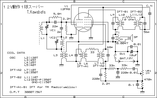
12K5 SE Stereo Amplifier. A simple 12K5-based low-power audio amp. Good for headphones, though I don't think it will drive much volume from a speaker. Although the site is in Japanese, the schematic can be read, and if you have any skill with the Japanese language (I don't) you may be able to discern some of this chap's technical insights.
-
12AE6 - 12CX6 Breadboard Regen. Another Japanese page, but the schematic is readable, and the photos (of a clever IC-style broadboarding system) gorgeous. The real problem with the article being in Japanese is that the coil specs are not readable, but you can probably figure them out using the usual resonance equations. For links to more circuits by this person (again, all in Japanese, but you can read the schematics and view the very nice photos) go here.
-
Space Charge AA5-Style Superhet. Yet another Japenese language page, this time of a complete high-performance BCB AA-5 superhet, made with space-charge tubes: 2 12AF6, 1 12AE6, 1 12AG6, 2 26A6, and 1 12K5. The unit runs on 26V or 12.6V. The two 26A6 tubes run in push-pull to get enough volume to drive the speaker. Nice pictures, and the schematic is readable. Again, the coils are obscure, but some tinkering should allow you to make something similar.
-
A 4-Tube Minimal Space-Charge Superhet. Still another BCB superhet circuit from the same Japanese chap who did the previous superhet. This one has only four tubes: A 12AD6 converter, a 12EZ6 IF amp, a 12AE6 detector/first audio, and a 12K5 audio "power" amp. Don't expect a lot of speaker volume with this one, but having worked a little with 12K5s, there's enough audio power (about 40 mw) to provide close-in listening.
-
A 12FR8 Pocket Tube Radio. Yet another gem in Japanese, this is a pocket receiver using a single 12FR8 diode/triode/pentode. It runs on 12V worth of penlight cells, but how long those last while sourcing 320ma (!!!) to the filaments is an interesting question. The problem here is that most of the details are in Japanese. There is a link to the schematic, but a direct link is here. The circuit is intriguing all by itself.
-
A 12V Homebrew Regen. By Al Klase N3FRQ. Very simple 1-stage regen using a 12DZ6, but adaptable to a number of other space charge tubes. Like most single-stage regens, this one works best with high-impedence (2000 ohm) headphones. If the schematic doesn't come up well in your browser, view it alone by right-clicking and selecting "View image" from the context menu (Firefox) or save the image to disk from the context menu in IE, and view it with any image viewer.
-
A 12DZ6 12V Reflex Receiver. By Al Klase N3FRQ. Extremely intriguing circuit: The signal passes through the tube twice, first at RF and then, after 1N34A diode detection, as audio. The circuit includes a tunable band-pass filter (for selectivity) that will be a bit of a trick to duplicate. As with the author's other design cited above, if the schematic doesn't come up well in your browser, view it alone by right-clicking and selecting "View image" from the context menu (Firefox) or save the image to disk from the context menu in IE, and view it with any image viewer.
-
12V Vacuum Tube Regenerative Receiver. Mike Branca W3IRZ uses a pair of 6BA6s in a two-stage receiver for 4.7-9.5 Mhz. The coil and capacitor are the oscillator tank from an ARC-5 (BC-457). The audio stage also worked using a 6AG5 and 6AU6.
-
12BH7A Separate Autodyne Receiver. The page itself is in Portuguese, but the schematic (a separate .gif) is perfectly readable. The author is listed as Hidehiko Komachi JA9MAT of Japan. The 12BH7A is a dual-triode, with one stage as an RF amp and another as a regenerative detector. One interesting feature of this circuit is the use of two varactor diodes as the bandspread tuning cap. An outboard "black box" audio amp (solid state, I suspect) drives a speaker.
-
Low-B+ Two-Tube Regenerative Shortwave Receiver. By Kees Talen K5BCQ.This is a sophisticated shortwave regen using two of the twin triode tubes like the 12U7, 12AU7, 12AT7, etc. that tunes from 2.5 - 22 MHz. Bands are changed by bandswitching a single coil on a military surplus ceramic coil form. Lots of controls, and probably very high-performance. Power supply is a husky 12V wall wart. The author has another regen design using more conventional battery tubes like the 1T4 running at 27V (3x9V batteries) here.
-
A Low-Voltage 2-Tube Regenerative Receiver. Very minimalist page consisting of the schematic and little else. Two 6C6 tubes with 1.5 to 3V on the plates! (I'm not sure I believe this, but I have the tubes and the sockets and it wouldn't take much time to lash it up!!) If you've built this circuit, please let me know, and post a page with photos.
-
A Low-Voltage Tube Hybrid Headphone/Line Amp. (612K PDF) This ambitious printed-circuit audio project by Pete Millett uses a pair of 12FM6 or 12AE6A space-charge tubes working into a pair of solid-state audio power amplifiers. Note that this is not a quick or a cheap project, but high-end audio that will take some work and care!
-
Low-Voltage 2-Tube Regen Receiver. By Kees Talen K5BCQ. This is one of the best space-charge receiver circuits out there: A 12U7 dual triode provides an RF amp followed by a regenerative detector, and a 12AL8 triode-pentode provides two stages of audio amplification into 600 ohm headphones. I've used the 12AL8 and I think it might be capable of driving a small speaker through an appropriate output transformer. Uses a tapped coil for bandswitching rather than several plug-in coils. Will take some work and care, but it looks mighty nice.
-
Norm's 12K5 Regen. Developed by Norman Leal, this AM BCB receiver uses a single 12K5 space charge tetrode with 12V B+. More discussion in the same forum on this thread, including photos of the radio built in an empty CD/DVD container—and the main tuning coil is wound around the 1/2" plastic post at the center!
-
Two 12V Valve MW Superhet. By Nick Pettefar M0NJP. Bare-minimum superhet circuit using two interesting low-voltage tubes: The 12FX8 pentagrid converter / triode and the 12AL8 triode / power pentode. Together they provide four stages: Converter, IF amp, first audio, power audio. (For small values of "power.") Detection is done with a silicon diode. This might make a reasonable AM tuner for use with an external power amp. Nick wound his own tapped oscillator coil but did not spec it in the schematic. You could probably swap in a commercial BCB oscillator coil.
Print Articles on Low-B+ Tube Technology
The articles shown below are listed in chronological order, with the earliest first. If anyone has a circuit not listed here that uses any 12V space charge tube or conventional tube operating with 20V or less on the plate, please contact me, so I can get a copy and add it to the listing. Many thanks to Michael Covington N4TMI for locating some of these ancient articles for me in the University of Georgia stacks. Also thanks to John Bauman KB7NRN for providing some of the scans out of his personal library.
You can find some of these publications on eBay, or on the used book services like ABE Books.
-
"Midget Portable Receiver" QST, October 1935, in "Hints and Kinks", p. 53. A type 49 tube as the detector and an unspecified triode as the audio amp in a 2-stage receiver by Roy Usher, VE4EA. A type 46 will also work. The tubes have 6V on the plates, but the battery is 13.5V, tapped in the middle. A separate 3V bias supply is used in the audio amp. This circuit inspired the one from Popular Mechanics for September 1936, below.
-
"The 'Elf', a 2-Tube Set for Beginners" Radio Craft, August 1936, p. 82. By C. W. Palmer. Another space charge circuit using a type 49 operating at 7.5 volts, with a second type 49 as an audio amp. The circuit as shown uses two separate 7.5V batteries for the B supply, such that the audio amp has 15V on the plate. The circuit uses a 5:1 or 10:1 audio interstage transformer, and a modified superhet antenna coil, but an appropriate BCB coil could be used. High-res scan of the article: CBZ archive. (1.7 MB) (Use Comical or QComicBook to view.)
-
"One-Tube Set Works on Six Flashlight Cells" Popular Mechanics, September 1936. A conventional regenerative circuit using a type 49 tube with 6V on both the plate and the control grid, and the screen grid used as the control grid. This is one circuit where "super-sensitive" high-impedence headphones are a disadvantage, because their DC resistance reduces the plate voltage! I think using 12V instead of 6V would fix that. BTW, the article explicitly attributes the concept (and most of the circuit) to Roy Usher, VE4EA, author of the article in the October 1935 issue. Page 1 (504KB) Page 2 (278KB).
-
"Amplifier Added to Flashlight Battery Set" Popular Mechanics, October 1937. This article adds a one-stage audio amp using a type 49 to the September 1936 receiver circuit, again at 6V. The circuit to the September 1936 set is given here as well, so if you have this one, you basically have both. Page 1 (941KB) Page 2 (366KB).
-
"One-Tube DX Short-Wave Set" Popular Mechanics, April 1938. A one-tube regen using a type 49 with 6V on the plate and the control grid. Regeneration is controlled by controlling the space-sharge potential on the control grid with a 200K pot. Unlike a lot of these old circuits, this one gives good specs on the coils, for four bands from 200 to 18 meters. Page 1 (498KB) Page 2 (493KB) Page 3 (279KB).
-
"Two-Tube Receiver Brings in Foreign Stations" Radio for the Millions, 1945, page 35. This is a one-stage regen followed by a one-stage audio amp, with both stages using 6C6 tubes. The 6C6 is a pentode, and in this circuit both the screen grid and the suppressor grid are connected to B+ as accelerators. They'd better be; in this circuit B+ is only 3 volts, and for local stations may be run with a B+ as low as 1.5 volts! (Note: Radio for the Millions has been reprinted and is available from Lindsay Books. Not listed online. Get their printed catalog.)
-
"Pocket Receiver for Sports Fans" Radio for the Millions, 1945, page 63. Uses a type 958 acorn tube in a superregenerative detector, running at 6V on the plate. The tube and its socket can be had at Antique Electronic Supply, though together they'll cost you about $18. The circuit is not intended for distance reception, but it's an interesting hack and I'll bet it would work better with 12V on the plate and some tweaking. (Note: Radio for the Millions has been reprinted and is available from Lindsay Books. Not listed online. Get their printed catalog.)
-
"Batteries Power Compact Emergency Receiver" Radio for the Millions, 1945, page 176. Typical regen followed by two stages of audio. Three 6C6 or 1SA6 tubes may be used. 9V on the plates, and the filament voltage is apparently how the gain of all three stages is controlled. Your big problem and expense here will probably be the two audio interstage transformers. (Note: Radio for the Millions has been reprinted and is available from Lindsay Books. Not listed online. Get their printed catalog.)
-
"Something New in High-Frequency Mobile Converters" QST, September 1956. Sophisticated 5-band dual-conversion design using a 12AF6 RF amp up front, followed by two stages of conversion using 12AG6 pentagrid converters. Bandswitching is accomplished using plug-in coils on home-made polystyrene forms. Inductance for all coils is given.
-
"Low Plate potential Tubes" Radio & Television News, January 1957. Some theory and history from Tung-Sol, including characteristic curves on the 12K5 power tetrode.
-
"Simple 12V Mobile Converter for 75 & 40 Meters" QST, July 1958, Hints & Kinks. Proves out NA4G's contention that "ordinary" tubes work at 12V by showing a 12SA7 metal converter in 12V service with a 3MC crystal.
-
"Mobile Converter - No B Plus" QST, August 1958. Very simple design for 75 meters only. 12AF6 RF amp followed by 12AD6 converter. Unfortunately, no inductance values are given for the slug-tuned coils.
-
"Converter Puts FM in Your Car" Radio-Electronics, August 1959. Basically a one-page review of the Gonset 3311 broadcast FM converter product. It includes a schematic, which is useful for biasing values and ideas, but coil and some cap values are not given, so reproducing the device whole will be problematic. Uses the 12EC8, 12EZ6, 12AD6, and 12AL5.
-
Several car radio schematics using space charge tubes are present in a book by Lou Garner called Transistor Circuit Handbook, published by Coyne Electrical School (Chicago) in 1960. Look for the section "Hybrid Automobile Receivers" on page 415. The circuits are all from real car radios, but the focus is on the power transistor audio finals, which were still a little exotic in 1960. The book is worth having, especially if your interests run to "classic" transistors (CK722/2N107/2N554 etc.) as well as tubes. Many copies can be found for sale at ABEBooks, often for as little as $4.
-
"Design of Mobile Receivers with Low Plate Potential Tubes" Electronics, August 19, 1960. Useful circuits for the 12EK6 amplifier and 12AD6 converter, for FM mobile up to 180Mhz. Mostly a design piece; the circuits given are conceptual more than duplicatable.
-
The Knight-Kit 12-in-1 product from about 1960 used a 12K5 space-charge tube in various circuits. The manual to this item shows up on eBay now and then and includes schematics.
-
"A Modulator-Powered Hybrid Transmitter" CQ, August 1961, p. 56. Bizarre circuit incorporating a 12K5 space-charge crystal oscillator followed by a 12AQ5 RF final, modulated by five transistors. The modulation provides all B+ to the final, helped by a couple of clamp diodes. I don't quite follow it, but from what I know it looks dicey, and the only part of interest, really, is the 12K5 crystal oscillator.
-
"A Crystal-Controlled Converter with Bandswitching" QST, March 1962. Two-tube converter, using the 12EK6 pentode as an RF amp in front of a 12AD6 pentagrid converter, with a switch swapping out a crystal and coil for each band. Specs given for all five bands. Main problem is the heavy use of now-unavailable iron-core ceramic coil forms. Fortunately, coil inductance values are given.
-
"Hybrid Receiver for the Locals" Popular Electronics, April 1962, p. 74. A hybrid AM BCB receiver using a 12AE6 space-charge triode for the RF portion of the circuit and a 2N321 transistor as an audio amp. The grid leak detector is not regenerative and I'm not guessing you'll get much performance from the unit, though it's quite simple. The antenna coil is wound on a disk of cardboard with slots cut in it, over-and-under style.
- "3-Way VHF-er" GE Ham News,
Vol. 17, no. 3, May-June 1962, page 1. By Jack Najork K9ODE. Intriguing
but probably unbuildable hybrid mobile AM and wideband FM receiver
tuning from 49-150 MHz using Mallory's now-extinct "Inductuner" spiral
tuning coils.
After a 12EK6 RF amplifier, a 12EK6 superregenerative detector
generates audio that is then "up-converted" to the AM BCB using a 12AD6
space-charge pentagrid converter. This upconverted signal is then fed
to a car radio for detection and amplification. A hybrid 12DS7/2N241A
push-pull audio power output stage is given in case you don't want to
use it in the car. The Inductuner is the killer here. If you have one
in the junkbox it might be worth a shot, but it's the lynchpin
component and can't easily be duplicated.
-
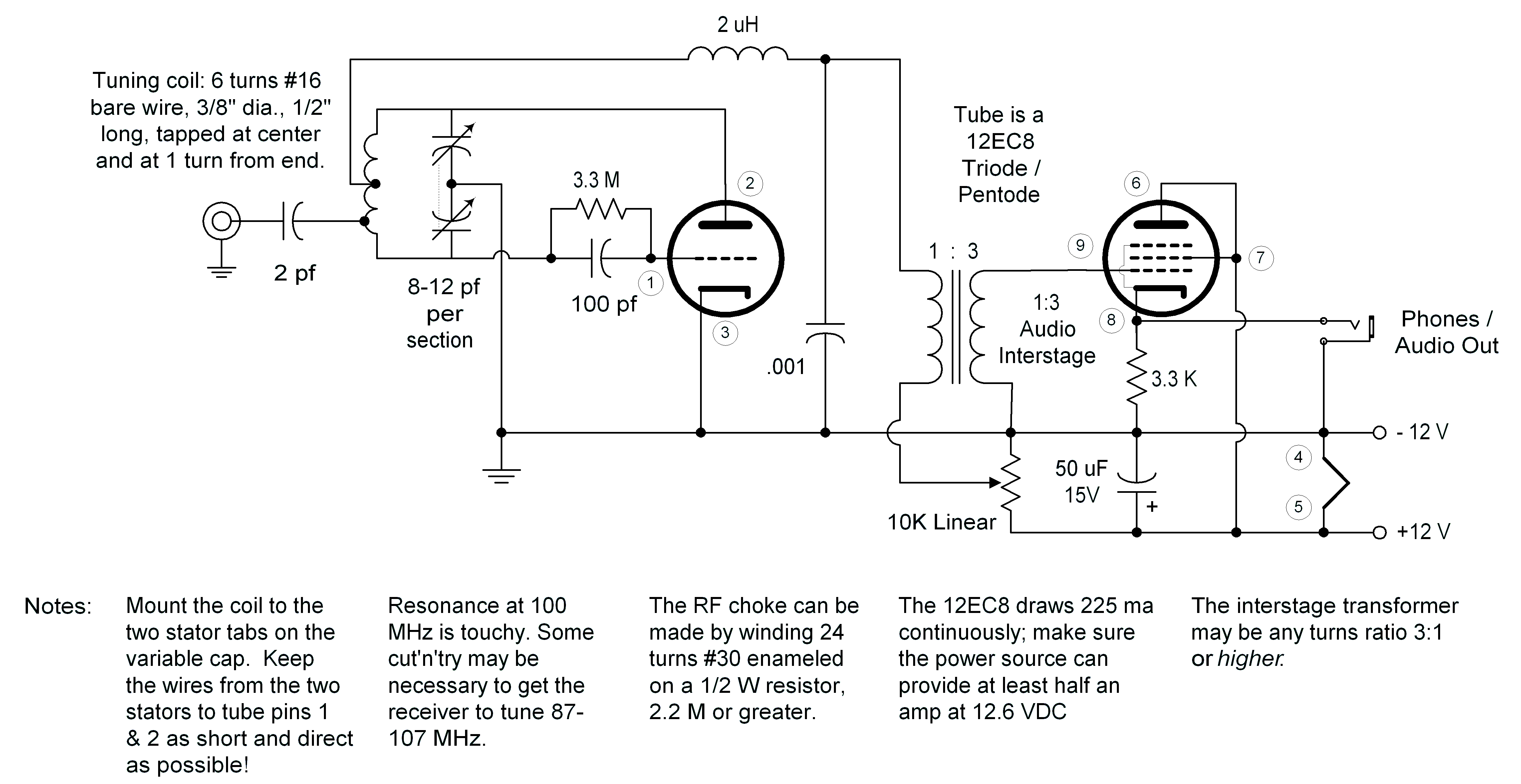
"One for the Road" Popular Electronics, July 1962, p. 44. A 9-pin, triode-pentode 12EC8 space charge tube works as a superregenerative detector and audio amplifier. Although designed for the AM avaiation band just over the FM broadcast band, superregens can slope-detect broadband FM and the circuit could be easily "slid down" to 100 MHz by adding another turn to the coil. A friend of mine built this circuit when I was in eighth grade, and although neither of us entirely understood how it could work with only 12V on the plate, I remember listening to planes coming in to O'Hare Field, and the signal was loud and clear. (This was in 1966; airliners use different radio bands and modulation systems now.) I recently (2007) built this circuit and it worked quite well, and brought in music from my local oldies FM station. (Note: Simple superregens are not hi-fi!) Here's the schematic as I built it (285K GIF) with values to receive down to about 100 MHz.
-
"A 10-Meter Mobile Converter" CQ, August 1963. Uses a 12AD6. No crystal; uses LC tuning. You could lash this up in an hour and it would be fun to try if you have local 10M AM activity. Add a few turns of L and you can pull it down to the 27 MHz CB band, where AM (and pandemonium) still reign, just as they did in the 1970s!
-
"A Complete Mobile Package, Part 2" QST, July 1964. Very sophisticated 5-band AM transmitter/conmverter package including switched RF amp, converter, and 1600KHz IF strip for use into a car radio. Basically the front end for a bandswitched superhet using space charge tubes. Uses our friends the 12EK6 and 12AD6. Part 1 of this series is a nice AM rig with a 2E26 final. Finding the 1600KHz IF cans will be a problem.
-
"An Inexpensive Mobile Converter" CQ, issue unknown. I copied this out of my mags for filing without taking note of the issue, but I would guess 1960-65 somewhere. Simple circuit with a 12BE6 and a 3Mc crystal, converts to 40 and 80. As usual, for car radios. Says 12AD6 will work as well.
-
"50-MC Converter with 12V Nuvistors" ARRL VHF Manual, 1965 Edition. 6M converter uses three 8056 12V Nuvustor tubes, with one acting as RF amp, one as oscillator, and one as mixer. The 8056 is electrically equivalent to the common 6CW4 except for the plate voltage. The circuit makes heavy use of those famous unobtanium ceramic coil forms, a 49.4 MHz crystal, and one of those marvelous BCB ferrite loopsticks that used to be everywhere but are now almost nowhere. Coil inductances are not given, alas. Prepare to cut'n'try. (You have a grid dipper, right?)
-
"10-Meter Mobile Converter" Electronics Circuits Handbook, Volume II, by Tom Kneitel K2AES. (Cowan Publishing, 1966.) This is basically the article of the same name from CQ, August 1963. (Cowan published CQ at that time.) LC-tuned 12AD6 converter.
-
"CB Converter for 12V" Electronics Circuits Handbook, Volume II, by Tom Kneitel K2AES. (Cowan Publishing, 1966.) Very similar to the article "10-Meter Mobile Converter" from CQ, August 1963. The only significant difference is the use of a 12AG6 converter instead of a 12AD6, and the LC values that set its frequency coverage.
-
"The Simple Superhet" QST, November 2003. Ron D'Eau Claire AC7AC. Modern treatment of an old idea: Convert signals to a standard IF frequency, and then use a regenerative detector at that frequency. The converter front end is a 12AD6, followed by a 12DZ6 pentode for the detector. Peculiarly, the audio amp is an LM386 chip amp—if I ever build this one, I'm going to change that to a 12K5 to keep the concept "pure." Bandswitched for 20 and 40M. The article is superb, BTW. Plenty of photos and very detailed construction tips.
-
"Those 12V Car Tubes" Tube Collector, December 2004. Ludwell Sibley. Good, detailed overview of the 12V space charge tube phenomenon, aimed at tube collectors but well worth hunting down by homebrewers. Has a nice table of the tubes themselves. Includes a simple circuit from Sylvania for a CB receiving converter, using the 12DZ6 tetrode and the 12EC8 triode-pentode. The magazine is very nice, by the way; subscription and back issue information can be had at the Tube Colectors' Association Web site, http://www.tubecollectors.org