
In 1960, the writing was on the wall: Tubes were being bested in every area by transistors, which did not require heater power, did not generate as much heat, and were a tiny fraction of the size. GE's engineers made an interesting decision: To give tubes one more shot in the war with transistors, and push off the inevitable end of the vacuum path for a few more years.
What GE did was combine multiple common tube types into "fat" tubes—as many as four in a single glass envelope, all heated from the same filament. The idea was to reduce the amount of power required to heat the tubes and the space they required on the circuit board, as well as the associated costs of multiple sockets. In a very crude way, GE was applying the concept of integrated circuits to tubes, and if solid-state technlogy had not advanced as quickly as it did in the first half of the 1960s, the Compactron idea might have been developed further, with even more tubes in a single envelope, with perhaps resistors and capacitors to implement resistance coupling networks for amplifiers. We'll never know, but Robert Casey has an interesting page speculating on a sort of "super-Compactron" implementing all tubes required for an "All-American Five" table radio in a single envelope. This was never done, but it would certainly have been possible.
In truth, Compactrons (first announced by GE in 1960) were designed almost completely for the color TV market. Table radios and Hi-Fi equipment represented much simpler design challenges for electrical engineers. (Some high-end Scott AM/FM tuners used Compactron tubes, but not many.) Color TVs are tough nuts to crack in many respects, and the transistors of the time (1960) were not quite as good as tubes, especially for high-voltage and VHF/UHF circuits. So GE's engineers took a look at the various elements of Color TV circuitry, and started combining compatible tube elements into single glass bottles.
The result is the catalog of Compactron tubes we know today. A good example is the 6AF11, a three-tube portmanteau consisting of a high-mu triode for AGC keyer service, a medium-mu triode for sync separator service, and a sharp-cutoff pentode for video amplifier service. The 6T9 is a hi-mu triode and power pentode combo representing the entire audio section of a simple TV set. (There was no stereo sound in TV technology at that time.) These sound very application-specific, but they're still just tubes, and they can be used for lots more than the TV circuits that they were designed for. The 6T9, for example, can work at RF frequencies up to 30 MHz, and there are a number of circuits using it for simple amateur radio CW transmitters, with the triode acting as a crystal oscillator and the power pentode as a 5W RF power amplifier. The 6AF11 is used in a popular regenerative all-band receiver circuit designed at GE and published in Popular Electronics in 1963.
The catalog of available devices grew over the first half of the 1960s. I have a PDF of the 1962 list from GE, as well as the much larger 1964 list. I don't know when new devices ceased to be added, but I do see that the 6Z10 (basically a complete TV audio section from discriminator to power audio amp)
was not present in the 1964 list. I'm guessing that new tubes may have
been added to the Compactron lineup as late as 1970, especially sweep
tubes and series-string variants of 6V types.
This idea of stuffing three or more active devices in a single envelope was not completely new. There is a battery tube, the 1D8-GT,
which combines a diode, triode, and power pentode into a single bottle.
The 1D8 has been around since 1939, and there is a less common 3V
filament version called the 3D8. It enabled the creation of cheap
3-tube AM BCB superhets, a good example of which was published in the September 1940 issue of Popular Science.
A 1A7 pentagrid converter feeds a 1A5 IF amplifier, which then pumps
the IF signal into the 1D8's diode and then its 2-stage audio
amplifier. The venerable Rufus P. Turner published an article in the
October 1955 Popular Electronics
called "1-Tube Wallop," which used a 1D8 to combine a diode BCB AM
detector with a two-stage speaker audio amp. Other (and I think far
better) 1D8 circuits are discussed here and here.
Compactron tubes are available in huge numbers, and quite cheap, for this reason: They were manufactured in huge numbers right before the bottom fell out of the tube market. Immense quantities survived, and now you can get extremely useful tubes like the 6AF11 and the 6T9 for a couple of bucks each, which is a fraction of what they cost (in inflation-adjusted dollars) in 1963.
Is This Really a Win?
So. Is stuffing as many tubes as possible in one glass bottle really a win? I think so, but there are a couple of downsides to using Compactrons in hobby projects:
-
The mix of tubes is not always precisely what you need, and if it isn't, one or more of those tube assemblies inside the bottle won't be useful. You may end up designing for what you have rather than with what you need, and while that's a subtle difference (and not always a bad thing) it's a real engineering challenge.
-
Point-to-point wiring to Compactron sockets can be tricky. Compactrons were developed late enough in tube history to have been intended for printed circuit wiring, not solder tab sockets. Components pile up around thoser solder tabs, making it absolutely crucial to plan the order in which components are soldered in, lest components soldered first block access to tabs needed later. Also, the solder tabs are very close together, making short circuits very easy to do without extreme care, especially when using larger components (think: one or two watt resistors) with larger gauge leads. The photo below (of my partially completed 6T9 stereo amplifier) will give you a sense for what I mean—and not all pins on the 6T9 sockets are used!
-
If you have some experience with tubes, keep in mind that the individual tube sections within a Compactron are often electrically identical to older, single-section tubes with similar functions. The popular 6T9, for example, is a combination of a 6AV6 triode section and a 6AQ5A power pentode section. The gated beam discriminator section of a 6Z10 Compactron is identical to the 6BN6. If you have any 6BN6 circuits or experience, you can apply that knowledge when using the 6Z10—and the power pentode section is (like the 6T9's) a 6AQ5A. The 6C10 is a three-section 12AX7, and the 6D10 is a three-section 12AT7. Get a late tube-era data book (Antique Electronic Supply has them for year 1974) and study it!

Compactron Tube Listing
In the table below is a list of all the generally useful 6V and 12V filament Compactron tubes that I know about. I'm omitting most of the Compactrons with odd series-string filament voltages (8V, 15V, 17V, 21V, 33V, etc.) because they require more fooling around to use, and if it's only the filament voltage that's different, you can use the non-filament specs for the 6V version. (I am listing a few that have no 6V or 12V filament versions.) I'm also omitting some of the tubes that are extremely specific to color TV service, like shunt regulators, just to avoid cluttering up the list with devices that hobbyists are not likely to use. There are a handful of types that I am omitting because I can't find good online data for them; oddly enough, the much-loved 6KE6 sweep tube is one of these.
One thing to keep in mind is that Compactrons were designed to have
very rugged filaments, and can be operated at +-20% of their rated
voltage. In other words, an 11-volt Compactron or a 13-volt Compactron
can both be run with 12.6VAC on the filaments. The 11V tube may run a
little hot, but unless you have an enclosed cabinet full of them I
don't think it'll be an issue.
Links to tube data are (mostly) to the wonderful NJ7P Tube Data Site. A (PDF) at the end of a tube description is a link to a PDF of the tube's full data sheet, which generally contains characteristic curves for the device. (Keep in mind that these are page scans and are often very large files, sometimes over 1 MB.) The PDF data sheets are (mostly) from Frank Philipse's tube data sheet pages. Tubes for which no links are present are Compactrons that I know exist (generally by finding them in tube-tester data books) but for which I have not yet found data online.
If you know of any other useful 6V or 12V Compactron tubes not listed here, please let me know!
|
Tube
|
Base
|
Description
|
| 6AC9 | 12GN | Dual Diode + Pentode |
| 6AC10 | 12FE | Hi-Mu Triple Triode |
| 6AD10 | 12EZ | Sharp-Cutoff Pentode + 10W Beam-Power Pentode |
| 6AF10 | 12GX | Dissimilar Twin Pentode |
| 6AF11 | 12DP | Hi-Mu + Medium-Mu Triode + Sharp Cutoff Pentode (PDF) |
| 6AG9 | 12HE | Medium-Mu Triode + Sharp-Cutoff Pentode |
| 6AG10 | 12GT | Gated Twin Hexode |
| 6AG11 | 12DA | Twin Diode + Twin Hi-Mu Triode (PDF) |
| 6AH9 | 12HJ | Medium-Mu Triode + Sharp-Cutoff Pentode |
| 6AK9 | 12GZ | Medium-Mu Triode + Hi-Mu Triode + Pentode |
| 6AK10 | 12FE | Triple Medium-Mu Triode |
| 6AL9 | 12HE | Medium-Mu Triode + Pentode |
| 6AL11 | 12BU | Sharp Cutoff Pentode + Beam Power Pentode |
| 6AR11 | 12DM | Semi-remote Cutoff Twin Pentode |
| 6AS11 | 12DP | Hi-Mu Triode + Medium-Mu Triode + Sharp Cutoff Pentode |
| 6AV11 | 12BY | Medium-Mu Triple Triode |
| 6AY11 | 12DA | Twin Diode + Twin Hi-Mu Triode |
| 6B10 | 12BF | Medium-Mu Twin Triode + Twin Diode |
| 6BA11 | 12ER | Medium-Mu Triode + Twin Pentode |
| 6BD11 | 12DP | Hi-Mu Triode + Medium-Mu Triode + Sharp Cutoff Pentode |
| 6BF11 | 12EZ | Sharp-Cutoff Pentode + 10W Beam-Power Pentode |
| 6BH11 | 12FP | Twin Medium-Mu Triode + Sharp Cutoff Pentode |
| 6BK11 | 12BY | Triple Triode |
| 6BN11 | 12GF | Sharp-Cutoff Twin Pentode |
| 6BV11 | 12HB | Dual Sharp-Cutoff Pentode |
| 6BW11 | 12HD | Twin Sharp-Cutoff Pentode |
| 6BY11 | 12EZ | Sharp-Cutoff Pentode + 10W Beam-Power Pentode |
| 6C10 | 12BQ | Hi-Mu Triple Triode |
| 6CA11 | 12HN | Dissimilar Dual Triode + Pentode |
| 6D10 | 12BQ | Hi-Mu Triple Triode (All Sections Identical) |
| 6FJ7 | 12BM | Medium-Mu Twin Triode |
| 6FM7 | 12EJ | Low-Mu Triode + Hi-Mu Triode |
| 6FY7 | 12EO | Low-Mu Triode + Hi-Mu Triode |
| 6G11 | 12BU | Sharp Cutoff Pentode + Beam Power Pentode |
| 6GA7 | 12EB | Diode + Pentode |
| 6GE5 | 12BJ | 18W Beam-Power Pentode (Sweep Tube) |
| 6GF5 | 12BJ | 9W Beam-Power Pentode (Sweep Tube) |
| 6GV5 | 12DR | 18W Beam-Power Pentode (Sweep Tube) |
| 6GY5 | 12DR | 18W Beam-Power Pentode (Sweep Tube) |
| 6HB5 | 12BJ | 18W Beam-Power Pentode (Sweep Tube) |
| 6HD5 | 12ES | 24W Beam-Power Pentode (Sweep Tube) |
| 6HE5 | 12EY | 12W Beam Power Pentode (Sweep Tube) |
| 6HE7 | 12FS | Diode + Pentode |
| 6HF5 | 12FB | 28W Beam-Power Pentode (Sweep Tube) |
| 6HJ5 | 12FL | 24W Beam-Power Pentode (Sweep Tube) |
| 6HS5 | 12GY | 30W Beam-Power Triode |
| 6HV5A | 12GY | 35W Hi-Mu Beam-Power Triode |
| 6HZ5 | 12GY | 35W Hi-Mu Beam Power Triode |
| 6J10 | 12BT | Gated-Beam Discriminator + 10W Beam Power Pentode |
| 6J11 | 12BW | Twin Pentode |
| 6JA5 | 12EV | 19W Beam-Power Pentode (Sweep Tube) |
| 6JB5 | 12EY | 15W Beam-Power Pentode |
| 6JC5 | 12EV | 19W Beam-Power Pentode |
| 6JH5 | 12JE | 35W Hi-Mu Beam Power Triode |
| 6JK5 | 12JE | 35W Hi-Mu Beam Power Triode |
| 6JM6 | 12FJ | 18W Beam-Power Pentode (Sweep Tube) |
| 6JN6 | 12FK | 18W Beam-Power Pentode (Sweep Tube) |
| 6JS6C | 12FY | 30W Beam-Power Pentode (Sweep Tube) |
| 6JZ6 | 12GD | 18W Beam-Power Pentode (Sweep Tube) |
| 6JZ8 | 12DZ | Medium-Mu Triode + Beam Power Pentode |
| 6KD6 | 12GW | 33W Beam-Power Pentode (Sweep Tube) |
| 6KN6 | 12GU | 30W Beam-Power Pentode (Sweep Tube) |
| 6K11 | 12BY | Medium-Mu Triode + Twin Hi-Mu Triode |
| 6LB6 | 12GJ | 30W Beam-Power Pentode (Sweep Tube) |
| 6LF6 | 12GW | 40W Beam-Power Pentode (Sweep Tube) |
| 6LG6 | 12HL | 28W Beam-Power Pentode (Sweep Tube) |
| 6LR6 | 12FY | 30W Beam-Power Pentode (Sweep Tube) |
| 6LU8 | 12DZ | Medium-Mu Triode + Beam Power Pentode |
| 6M11 | 12CA | Twin Hi-Mu Triode + Sharp Cutoff Pentode |
| 6MF8 | 12DZ | Hi-Mu Triode + Beam Power Pentode |
| 6MJ8 | 12HG | Medium-Mu Triple Triode |
| 6MN8 | 12HU | Hi-Mu Triple Triode |
| 6MY8 | 12DZ | Medium-Mu Triode + Pentode |
| 6Q11 | 12BY | Twin Hi-Mu Triode + Medium-Mu Triode |
| 6T9 | 12FM | Hi-Mu Triode + 12W Beam Power Pentode |
| 6T10 | 12EZ | Sharp-Cutoff Pentode + 10W Beam-Power Pentode |
| 6U10 | 12FE | Twin Medium-Mu Triodes + Hi-Mu Triode |
| 6Y10 | 12EZ | Dissimilar Dual Pentode |
| 6Z10 | 12BT | Gated-Beam Discriminator + 10W Beam Power Pentode |
| 12AC10A | 12FE | Except for filament voltage, identical to 6AC10 |
| 12AE10 | 12EZ | Sharp-Cutoff Pentode + 10W Beam-Power Pentode |
| 12AL11 | 12BU | Except for filament voltage, identical to 6AL11 |
| 12BF11 | 12EZ | Except for filament voltage, identical to 6BF11 |
| 12BV11 | 12HB | Except for filament voltage, identical to 6BV11 |
| 12HE7 | 12FS | Except for filament voltage, identical to 6HE7 |
| 12JF5 | 12JH |
17.5W Beam Power Pentode (Sweep Tube) (PDF) |
| 12JN6 | 12FK | Except for filament voltage, identical to 6JN6 |
| 12JS6 | 12FY |
30W Beam-Power Pentode (Sweep Tube); see 6JS6C |
| 12JZ8 | 12DZ |
Except for filament voltage, identical to 6JZ8 |
| 12G11 | 12BU | Except for filament voltage, identical to 6G11 |
| 12GE5 | 12BJ | Except for filament voltage, identical to 6GE5 |
| 12GV5 | ||
| 12T10 | 12EZ | Except for filament voltage, identical to 6T10 |
| 23Z9 |
12GZ |
Dual Triode + 7W Beam Power Pentode (PDF) |
| 5890 | 12J | Remote-Cutoff Pentode Regulator |
| 7984 | 12EU | 46W RF Beam-Power Pentode |
| 8149 | ||
| 8150 | ||
| 8156 | ||
| 8950 | 33W Beam-Power Pentode. Heater 13VAC/DC @ 400ma | |
| N2ED | ||
| N30EL | Probably identical to 6LF6 |
There is also a photoconductive sensor cell manufactured
(circa 1963) by GE in a Compactron envelope. It's type Z-2946, and what little I know about it is here.
If
you ever run across a data sheet, please let me know. I have heard that
there are a couple of fluorescent indicator ("magic eye") tubes on the Compactron base, but have not confirmed this.
Compactron tube sockets (both solder tab and printed circuit types) are reasonably common at Antique Electronic Supply and on eBay.
"9-Pin Compactrons": Novars and Magnovals
Every so often I hear talk of "9-pin Compactrons." Technically those don't exist; all Compactron tubes have 12 pins. However, in 1962 RCA introduced a line of tubes called Novar. These are all-glass tubes with nine .038" (1.2mm) pins on a base larger than that of the familiar 9-pin miniature. RCA introduced them for use in audio equipment, and the motivation may have been to create a larger base and bulb for greater power dissipation. Most of the Novars I've seen have been power pentodes like the 7868, or color TV rectifiers.
There's something to careful of with Novar tubes. A very similar
line was introduced in Europe at about the same time. These were called
Magnoval tubes, and they have nine pins on the same diameter circle.
However, and crucially, Magnoval tubes have larger pins, at .046"
(1.27mm). If you plug a Magnoval tube into a Novar socket, the larger pins will damage the pin contacts on the socket.
You can wreck the socket of a late-era tube tester by trying to test a
Magnoval in the Novar socket. Before you test what you think is a Novar
tube, put a mic or a digital caliper on those pins!
There were not as many Novar tubes as Compactrons, and they were never very popular. Sockets are more difficult to find, though I've seen them online. Sellers sometimes claim that a single socket will work for both Novar and Magnoval, but that's not true. The larger Magnoval pins will damage any socket designed for Novar tubes, and Novar tubes will rattle around in any socket designed for Magnoval pins.
Safety Issues for High-Voltage Tubes
It's important to say right here up front: The voltages you must use in Compactron tube work can kill you. Years ago, the dangers of high voltage were common knowledge among electronics people, because high voltage was present in virtually everything you could call "electronic." However, over the past forty years, semiconductor technology operating at 12V or less has taken over hobby electronics. We've gotten very used to poking at circuit lashups with our bare fingers to try and spot bad solder joints or to detect overheating components. To stay alive, you're going to have to learn a whole new set of techniques, and work by them religiously:
-
If you sit on a stool at your bench, make sure the stool's legs are insulated from the floor using rubber "crutch tips" or something similar. In general, if you can find an all-wooden stool to sit on, so much the better.
-
Put nonconductive plastic knobs on all controls.
-
Once power is on to a project, don't touch anything "behind the panel" with your fingers.
-
Don't probe around inside projects with metal tools unless you're double-sure that power is unplugged. Don't settle for "off." Even if the handles are insulated and you don't get a shock from the circuit, if you bridge high voltage to negative or ground, you can damage the tool.
-
Even after power is unplugged, before you begin sticking your fingers into a project, bleed off any charge that might remain in any filter capacitors. I made up a tool which is simply a 27,000-ohm, 10 watt wire-wound power resistor mounted on a length of wood dowel, with the resistor's leads sticking straight out for about an inch or a little more. This should be good for caps holding as much as 550VDC. To use it, bend the resistor's leads so that you can easily bridge the hot lug on the cap to ground. Then bring the resistor's leads in contact with the hot lug and ground and hold it there for about ten seconds. By that time, no dangerous charge will be left in the cap.
Drawing Your Own Tube Schematics with Visio
If you modify published tube circuits before you build them, it's always a good idea to redraw them so you don't forget how the circuit on the bench differs from the one in that old article in QST. There's a very nice drawing program called Visio (now owned by Microsoft) that I've been using to draw schematics for over ten years now. Older versions can be had on eBay for as little as $20, and in fact the version I use—Visio 2000—is now six years old and still perfectly useful. (The latest versions require product activation, which I cannot abide, but in truth there's little in the newest Visio versions that isn't in Visio 2000. Just don't use Visio 1.0.)
I created a stencil file full of tube pinouts, including all the common tube types (dual diode, triode, tetrode, pentode, and so on) and all you need to do is drag them off the stencil and start connecting the leads. (Visio comes with stencils for all the common components like resistors, capacitors, and inductors.)
You can download the stencil file here. It has stencils for the several earlier versions of Visio, but the Visio 5 stencil works fine with Visio 2000 and later versions.
Compactron Tube Material on the Web
-
Multi-Function Compactrons Promise 2-Tube Radio. This is the news release from GE that started it all, way back in July, 1960. The most interesting thing is that the two tubes that GE's engineers promise in the news release (and are said to be available in sample quantities) never went into production, as best I know.
-
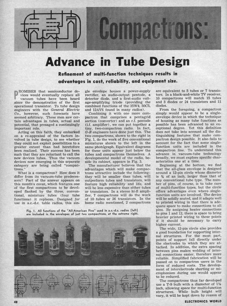
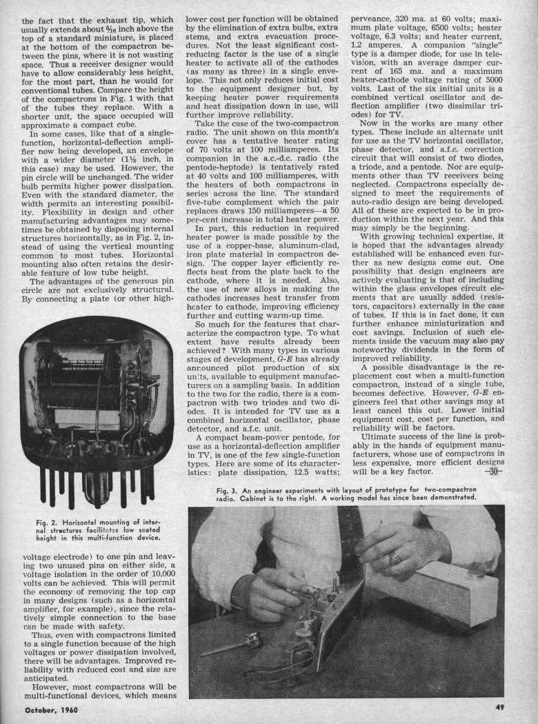
Electronics World published an announcement of GE's Compactron line in their October 1960 issue. Not much here to help homebrewers, but it's an interesting item, and it mentions "the unit shown on the cover" which is apparently the experimental 2-Compactron AA5 that GE created with a couple of their unreleased multifunction tubes. I'm looking for that mag, and when I find it I'll post a scan of the cover here. In the meantime, here are Page 1 and Page 2 of the article itself.
-
Audio Amplifiers from TV Compactrons. A nice simple 2-watt mono circuit from Wade Stanfill that may be constructed using any of a (long) list of Compactron tubes. Wade provides plenty of tips for jiggering the circuit based on what you have in terms of transformers. If you want to try a simple Compactron audio amp and have a little experience "rolling your own" with tubes this is a very good place to start.
-
Min-Amp. By Jon Stanley. A simple 1W audio amp built on an Altoids box, with a second Altoids box housing the HV power supply. The tube is a 6LU8.
-
A 6EM7 Headphone Amp. An experimental high-fidelity audio amp intended to drive headphones rather than speakers.
-
N1NKM's Homebrew 1-Tube AM Radio. A fairly sophisticated 3-stage BCB radio using the admittedly odd 15BD11 tube, which is what the author had in the junkbox. A 6V version of the same tube exists (the 6BD11) and may be easier to use, and certainly easier to light up.
-
Compactron AA5 AM Tube Radio by Bob Casey WA2ISE. Bob re-implements the classic All-American Five AM receiver using three Compactrons. The three tubes are the 11AR11, the 8B10, and the 38HK7. Lots of theory, graphs, and practical advice.
-
David's Duodecal Delight by Dave Schmarder. An interesting loudspeaker receiver for AM BCB using the 12AE10 dual pentode. The sharp-cutoff section is used for the receiver detector, and the beam-power section is the speaker amplifier. The coils are wound on spider forms, which will take some fretwork but are very cool if done well. The receiver as Dave built it is absolutely gorgeous.
-
One-Tube AM Transmitter by Bob Weaver. A single 6M11 provides a triode for an audio amp, a triode for an oscillator on the AM BCB, and a pentode as a screen-modulated power amp. The idea is to "broadcast" audio sources like records or computer sound cards into classic radios. This sort of gadget was once popular for playing phonograph records into a nearby radio (which generally had far better audio amps and speakers than inexpensive record players) and was called a "phono oscillator."
-
The Squirrel Monkey One-Tube Guitar Amp by Forrest Cook. A 6AF11 puts out about three watts, which I can attest (by experience with my own 6T9 Compactron stereo amp) is more than enough for guitar practice and ordinary audio listening. Forrest built his amp in a steel electrical junction box, a trick I am amazed I never hit upon in 46 years of electronics tinkering.
-
An Ultra-Linear 6T9 DIY Tube Amplifier. This is a tweak to the author's classic 6T9 audio amp to improve linearity. There's a forum on the same site with lots of discussion of this circuit and related tube-amp audio topics here.
Compactron Projects in Books and Magazines
This list of articles and citations were all originally published in print books and magazines, but a very few have been scanned and mounted on the Web. You can find some of these publications on eBay, or on the used book services like ABE Books.
-
"Introducing the Compactron," Popular Electronics, August 1961, P 45. GE's Receiving Tube division fielded a number of articles on the tubes at about this time, writing by staff engineers, and this was the first. It uses a 6D10 triple triode (basically, three identical trodes very similar electrically to those in a 12AT7) in a three-stage circuit covering the FM broadcast band, with the stages used as an RF amp, superregenerative detector, and headphone audio amp. A similar but more sophisticated circuit was published the very next month, also from GE. Hands-on Report: I built this circuit in November 2008, and it worked right off. One thing needs tweaking: The radio tunes from about 60 MHz to about 115 MHz. The FM BCB lies in one small portion of the capacitor's full swing, and the capacitance in the tank circuit needs to be tweaked. There are also hand-capacitance effects, which often occur when both sides of a tuning cap are isolated from the chassis.
-
"Compactron VHF Receiver," Popular Electronics, September 1961, P 45. A 6D10 triple triode tube provides an RF amp, superregen detector, and audio amp. The article claims that the circuit will detect both AM and FM circuits, but narrow band FM doesn't detect nearly as well with a "rushbox" as AM. The article is also by an engineer from GE, which was pushing Compactrons very hard at that point.
-
"Compactron Frequency Calibrator," Popular Electronics, July 1962, P. 75. By the legendary Herb S. Brier W9EGQ, this circuit uses a single 6D10 triple triode to generate marker signals either every 100 KHz or every 10 KHz, depending on a switch setting. One triode section is used as a 100 KHz crystal oscillator, and the other two act as a multivibrator oscillator that modulates the 100 KHz output such that 10 KHz heterodynes are generated as well, up through about 30 MHz.
-
"KCS AmateurBand Receiver." by Norman L. Morgan W7KCS/9. From GE Ham News. Part 1, Nov/Dec 1962. Part 2, Spring 1963. (Many thanks to Olivier Ernst for the scans.) The bulk of both issues is taken up by a description of an extremely sophisticated double-conversion superhet 5-band amateur receiver using four compactrons and four miniature tubes. Some good design ideas here, but I doubt you could duplicate the circuit today given all the unobtanium coil forms, odd IF cans, and mechanical filter. And I've often wondered how many guys actually built projects like this, even back in 1963.
-
"One Receiver, All Bands," Popular Electronics, January 1963, P 39. A 6AF11 dual triode/sharp-cutoff pentode provides a regenerative detector and two stages of audio. Hands-on Report: I actually built this as a twelve-year-old in 1964, and found it problematic then, though how much of that was my youthful inexperience I don't know. (Photos of my 1964 unit are here and here.) It should work modestly well, but the plug-in coil forms cited are no longer available and you'll have to recalculate the coils for whatever forms you can find. It was also written by a GE staff engineer. The same circuit was published in the 1965 GE Hobby Manual, in case you have that in a pile somewhere. The article has been scanned and posted online, at this page. Look for "6AF11: P. Hatfield". The Hobby Manual article has also been scanned and posted here.
-
"License-Free FM Transmitter," Electronics Illustrated, July 1964, P 47. Harry Kolbe presents a low-power, hi-fidelity FM BCB transmitter using a 6C10 triple-triode Compactron for its audio stages, and an ECC85/6AQ8 dual triode as a Colpitts oscillator and reactance tube modulator. Circuits like this used to be common: One section of the ECC85 becomes part of the capacitive voltage divider governing the oscillator frequency of the other half. By changing the audio input to the reactance triode, its reactance changes, thus changing the oscillator's frequency. Add an antenna and you've got a transmitter with a 500-foot range. Note: This is a pretty complex circuit for a magazine construction article!
-
"Integrated Stereo Amplifier," Electronics Illustrated, July 1964, P. 42. Walter Morrow gives us an ambitious (for a pulp magazine) stereo amplifier project that for each channel uses A 6C10 Compactron for the preamp stages, half a 12AX7 for the driver, and an ECLL800 for the phase inverter driving two power pentodes in push-pull, delivering ten watts to the speakers. The ECL800 is interesting all by itself: It's a species of Compactron in an ordinary 9-pin miniature package containing a triode and two power pentodes. This is a difficult (and expensive) project, but if you want to move beyond a very simple tube amp it might not be a bad way to go, but plan on spending big on the transformers.
-
"The Stereo S'Lector," by Alton B. Otis, Jr, Popular Electronics, September 1964, P 73. The author uses a high-gain triple-triode 6D10 to sense the presence of the 19 KHz subcarrier on stereo FM broadcast signals, and trip a 4PDT relay when a subcarrier is sensed. This may seem odd, but FM stereo was very new in 1964, and separate multiplex adapters were often added on to existing hi-fi FM tuners to receive a stereo signal. Subcarrier sense relays were present in high-end FM tuners and did basically the same thing. The only odd part is the JW Miller 1354 19 KHz oscillator coil, and I've seen these for sale here and there. Not a very practical project in 2008, but an interesting circuit nonetheless.
-
"The Compact BCer" by Homer Davidson, Electronics Illustrated, September 1964, P 32. Relatively simple AM broadcast regen (not shortwave!) using a single 6AL11 pentode/beam power pentode tube as a detector and speaker amplifier. The main coil is a slug-adjustable Fifties-style ferrite loopstick with a tickler winding added. The newer, non-adjustable transistor radio loopsticks will probably work in the circuit, but as they are not adjustable, you may have to pull windings to resonate an arbitrary variable capacitor. (Look on eBay for loopstick antennas. Most I've seen are non-adjustable, but you just might get lucky.)
-
"6 Meter Heterodyne VFO Transmitter" by Bill Hoisington K1CLL, 73 Magazine, April 1965. Clever AM/CW transmitter using a 6AF11, with the two triode sections working as two oscillators, one crystal-controlled at 49 MHz, the other variable at 3 MHz. The pentode section acts a a mixer, allowing the output frequency to be controlled across about 2 MHz on 6M. The mixer puts out about one watt of RF, which is then fed to an 815 dual power pentode working push-pull. The output stage is an old-style link. Bill does not specify an output power level, but whatever comes out of an 815 (which I have in the drawer but havepush-pull RF output at VHF, it would be useful to look at a few similar circuits in ARRL handbooks circa 1950-1960.
-
"One Compactron Regulated Power Supply" GE Hobby Manual, 1965, P 185. A fascinating circuit using a 6JZ8 medium-mu triode/power pentode. It's a variable voltage power supply that will give you 150-250 volts regulated, sourcing a maximum of 60 milliamps. Given that solid-state regulators capable of 250V output are fairly rare (though I have one somewhere) this would be a useful and educational gadget to build.
-
"Two Compactron Stereo Amplifier" GE Hobby Manual, 1965, P 101. Nice amp using two 6T9 triode/power pentode tubes. Designed for high-level crystal phonograph input, but you can jigger the input network to take almost any kind of audio. Hands-on Report: I built this circuit in 2005 for amplifying computer audio, and it works beautifully. I added a balance control and put it all in one box, amp and power supply both. My modified schematic can be found here (Flash SWF format) with photos here.
-
"The Shoebox II Linear" by John J. Schultz W2EEY, CQ, July 1967, P. 76. Bare-bones 5-band linear using four 6HF5 sweep tubes in parallel. Nothing exotic in the circuit apart from Miniductor stock. Hands-on Report: I built this in 1974, just after I got my General and had scrounged an ancient Central Electronics 10B SSB exciter. It was my first power amplifier project and I could never get it to "calm down." Sweep tubes are naturally "hot" at RF, but I've used similar tubes since then without trouble. My guess is that I made all sorts of mistakes in construction, naive as I was about power tubes at RF in 1974. Alas, I dumped the gadget when I moved away from home in 1976, else I would try to reverse-engineer my mistakes.
-
"The Unicorn" by Robert E. Kelland, Elementary Electronics, January/February 1970. A brilliantly basic superhet using a single 6M11 dual triode/pentode. Ok, they cheat a little by detecting the converted signal using an external solid state diode, but it's still a fascinating circuit. The big kicker on the parts side, as with a lot of other projects from this era, is the tunable ferrite loopstick. The oscillator coil and single IF transformer are nothing peculiar and can be scavenged from a dead AA5 or ordered as "universal replacements" from AES. The article has been scanned, and is available online. Page 1. Page 2. Page 3. Page 4. Page 5.
-
"A 10-Watt, One-Tube Transmitter" QST, March 1971, P 25. Another great Lew McCoy circuit. Hands-on Report: I've built this circuit twice, once point-to-point on a chassis circa 1995, and again using printed circuits in 2000. Worked great both times. It's a very simple crystal-controlled CW transmitter using the 6T9 triode/power pentode tube as a Pierce oscillator and power amp. It will give you ten watts input and about five-six watts output on CW. Like many QST circuits of the time it uses Miniductor stock, but for the PC board version I calculated and wound my own plug-in coils on vitamin bottles and it worked just fine. The circuit was also published in the 1973 ARRL Handbook.
-
"Build a Vacuum Tube Amp" Nuts & Volts, August 2004, P 50. Simple (maybe too simple) circuit using two 6T9 triode/power pentode tubes. There's no balance or tone controls, since the amp was designed to amplify audio from a computer sound board. The author makes a nice parts kit and circuit boards available for it, and if you're not experienced with tube construction, this would be an excellent place to start. See the author's Web site.
-
"The Six Tee Nine Tube Amp" by Randy Miller, Audio XPress, October 2007. Two 6T9's operating in push-pull provide 8-10W audio output. This is a mono amp; you'd need to make two for full stereo. One nice touch is that he doesn't use interstage transformers between the triode and pentode stages, cutting the cost of reproducing the circuit. Another nice touch is using 8.2V zeners to establish cathode bias, eliminating the degenerative feedback found in cathode resistor biasing schemes.The article may be downloaded in PDF format (500KB) here. There is a correction to be made to the published schematic: C3 and C4 should both be .022 uF and not .22 uF as published.
-
"The Compactron Vackar VFO" Electric Radio, May 2009, P 8. By Tom Marcellino, W3BYM. The circuit was designed specifically for AM work using the Johnson Viking transmitters, but I see no reason it couldn't be used with or adapted for other 50s designs. A single 6M11 dual triode/pentode provides the pentode oscillator, a cathode follower, and a voltage amplifier. The article is extremely detailed, and even includes a suggested socket layout so that all the many parts connecting to the Compactron socket will fit!